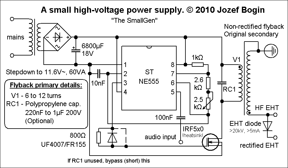
Transformator Tesla Na Ne555

The ‘NE555’ Timer Chip There is an exceptionally useful chip designated by the number 555. This chip is designed to be used in oscillator and timer circuits. Its use is so widespread that the chip price is very low for its capability. It can operate with voltages from 5 Volts to 18 Volts and its output can handle 200 mA. It takes 1 mA when its output is low and 10 mA when its output is high. It comes in an 8-pin Dual-In-Line package and there is a 14-pin package version which contains two separate 555 circuits.
The pin connections are: This device can operate as a monostable or astable multivibrator, a Schmitt trigger or an inverting buffer (low current input, high current output). Here it is wired as a Schmitt trigger, and for variation, it is shown triggering a triac which will then stay on until the circuit is powered down (an SCR could be used just as well with this DC circuit): And here, a monostable: And here are two astables, the second of which has fixed, equal mark/space ratio and the first a high output voltage time determined by Ra + Rb and a low voltage output time determined by Rb (2:1 in this case): Note: The high leakage of large value electrolytic capacitors prevents them being used with high value resistors in timing circuits. Instead, use a smaller capacitor and follow the timing circuit with a “divide-by-N” chip to give accurately timed long periods. Not all 555 chips have a manufacturing quality sufficient for them to operate reliably above 20,000 Hz, so for the higher frequencies the chip needs to be selected after testing its actual performance. We can also wire the 555 to give a variable mark/space ratio while holding the frequency of the oscillation fixed: The output waveform changes drastically as the variable resistor is adjusted, but the frequency (or pitch of the note) of the output stays unaltered.
555 have been known to us for many centuries, the precise nature of the. When t e transformer terminal T, is alternately electri ed, currents traverse the open. Is playing at d d and the sudden discharges are p)assed through the bars na,. Power up the Tesla's transformer primary winding is the inverter bridge or half-bridge comprises a pair. The control system is based on an chipset NE555, but it.
A variable-frequency version of this circuit can be produced by changing the 33K resistor to a variable resistor as shown here: Here, the 33K resistor has been replaced by two variable resistors and one fixed resistor. The main variable resistor is 47K in size (an almost arbitrary choice) and it feeds to a second variable resistor of 4.7K in size. The advantage of this second variable resistor is that it can be set to it’s mid point and the frequency tuning done with the 47K variable. When the frequency is approximately correct, the 4.7K variable can be used to fine tune the frequency. This is convenient as the small variable will have ten times more knob movement compared to the main variable (being just 10% of its value).
BELAJAR MEMBACA CEPAT DENGAN MEDIA FLASH CARD UNTUK ANAK USIA DINI. File BELAJAR MEMBACA CEPAT DENGAN MEDIA FLASH CARD UNTUK ANAK USIA DINI ini merupakan berkas yang kami sediakan untuk para Pengajar terutama Guru, guna melengkapi dokumentasi atau sebuah bahan yang bisa dijadikan sebagai referensi dalam pelaksanaan kegiatan proses belajar mengajar atau pekerjaan kantor lainnya. Secara umum berkas ini berformat doc. (word), namun bisa saja berbentuk excel (.xlxs) dan PDF. Flash card belajar membaca anak paud.
Obviously, it is not necessary to have the fine-tuning variable resistor, and it can be omitted without changing the operation of the circuit. As the 47K variable resistor can be set to zero resistance and the 4.7K variable resistor can also be set to zero resistance, to avoid a complete short-circuit between output pin 3 and the 50K Mark/Space variable resistor, a 3.3K fixed resistor is included. In this circuit, the frequency is set by your choice of the resistor chain 47K + 4.7K + 3.3K (adjustable from 55K to 3.3K) and the 100nF (0.1 microfarad) capacitor between pin 6 and the zero volt rail. Making the capacitor larger, lowers the frequency range.
Downloads: A new file has been added by Mick: Audi and VW Radio Code Calculator Audi and VW Radio Code Generator Calculator Unlocker Download this FREE Audi & VW tool for unlocking your radio after you have lost or forgotten your radio code! Audi vw calculatorexe download full.
Making the resistors larger, also lowers the frequency range. Naturally, reducing the size of the capacitor and/or reducing the size of the resistor chain, raises the frequency. One 555 chip can be used to gate a second 555 chip via its pin 4 ‘Reset’ option.
You will recall that we have already developed a circuit to do this using two astables and a transistor. We also generated the same effect using four NAND gates. Here, we will create the same output waveform using the more conventional circuitry of two 555 chips: Both of the 555 circuits can be bought in a single 14-pin DIL package which is designated ‘556’. There are many additional circuit types which can be created with the 555 chip. If you wish to explore the possibilities, I suggest that you get a copy of the book “IC 555 Projects” by E.A.